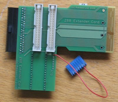
 | With no Z88 Memory card plugged into the Z88 Extender card
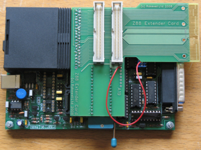
- Connect the A19 lead
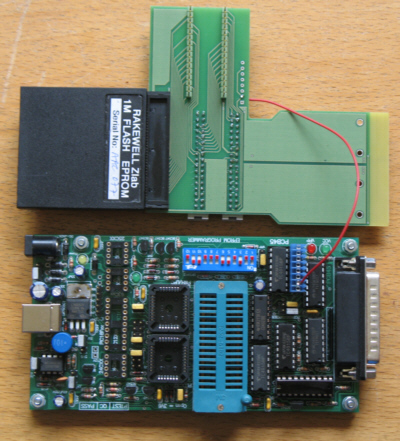
- Connect power to the EPROM programmer
- Connect to the PC and
- Initialise the EPROM Programmer
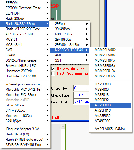
Select the chip you wish to use. In this example we are using the Am29F080 1M Flash TSOP chip.
Now plug in the Z88 Memory Card. |
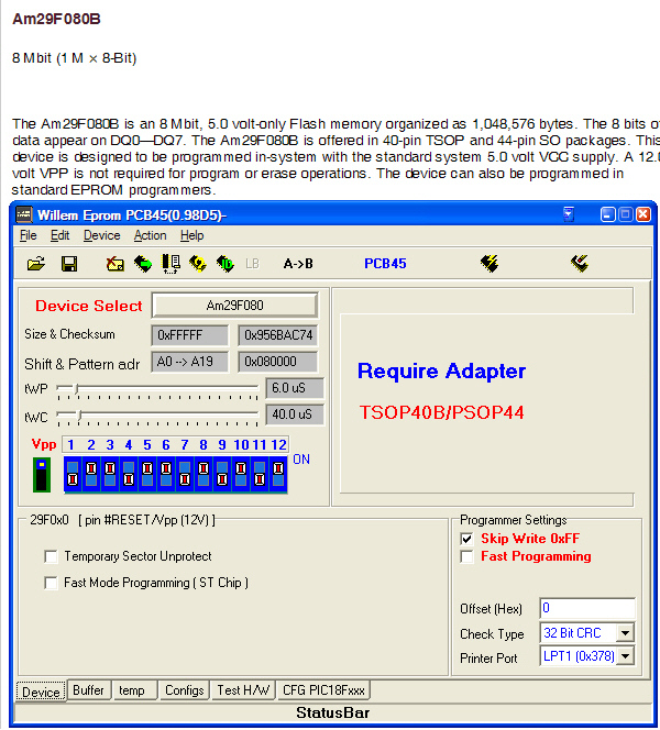 |
So here is the screen on the chip.
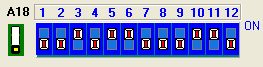
Do we take any notice of the switch settings for the physical settings given for the TSOP40B/PSOP44? No Just use the commands like
- Chip type
- Read Data
- Verify Data
|
AM29F040B - 512K Flash
|
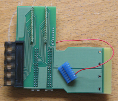
With no Z88 Memory card plugged into the Z88 Extender card
- Connect the shorting connector
- Connect power to the EPROM programmer
- Connect to the PC and
- Initialise the EPROM Programmer
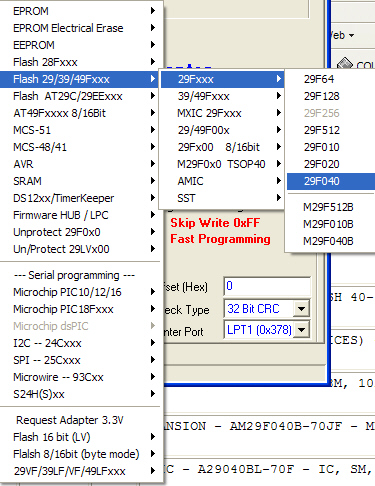
Select the chip you wish to use. In this example we are using the Am29F040 512K Flash chip.
Now plug in the Z88 Memory Card. |
AM29F040B - 512K Flash
|
With no Z88 Memory card plugged into the Z88 Extender card
- Connect the shorting connector
- Connect power to the EPROM programmer
- Connect to the PC and
- Initialise the EPROM Programmer
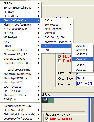
Select the chip you wish to use. In this example we are using the AMIC A29040 512K Flash chip.
Now plug in the Z88 Memory Card. |
|
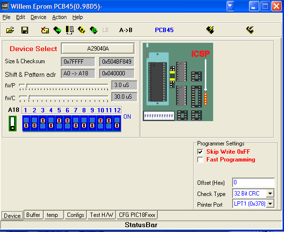
Here is the view of the AMIC 512K Flash chip.
REMEMBER TO IGNORE THOSE SWITCH SETTINGS |
Other
devices may be selected, like RAM, EPROM and the INTEL Flash chip, but
REMEMBER TO IGNORE THE PHYSICAL DETAILS given for ANY devices you are
using with this card.
Availability
Only a few cards are being manufactured, so if you are interested,
please let us know to discuss pricing and other such matters.
|